Induction Loop Systems: Loop Questionnaire
Induction Loop Testing Equipment
 Superloop
PRO III Induction Loop Assistive Listening System -- Spec Sheet
Superloop
PRO III Induction Loop Assistive Listening System -- Spec Sheet 
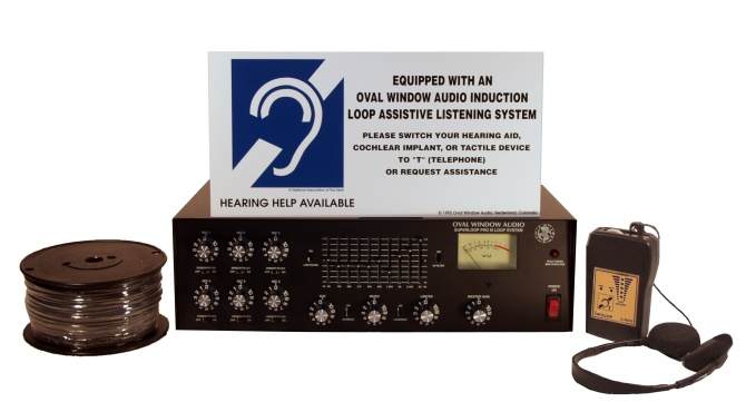
The Superloop PRO III system contains the following components:
- One Superloop PRO III loop amplifier
- One 500 foot spool of 14 gauge loop wire.
- One Induction Loop Receiver with headphones & LED signal display
- One wall mountable sign
- Instructions
 The Superloop
PRO III is a stand-alone induction loop assistive listening system
with a built in 8 channel mixer and one-third octave graphic
equalizer.
This system is most often used in large conference rooms and other
sites
where there is no sound system and a stand alone induction loop system
is required. The Superloop PRO III also interfaces easily with
existing
sound systems and is compatible with all telecoil-equipped hearing
aids,
cochlear implants and induction loop receivers. (Click
on photo to view enlarged image.)
The Superloop
PRO III is a stand-alone induction loop assistive listening system
with a built in 8 channel mixer and one-third octave graphic
equalizer.
This system is most often used in large conference rooms and other
sites
where there is no sound system and a stand alone induction loop system
is required. The Superloop PRO III also interfaces easily with
existing
sound systems and is compatible with all telecoil-equipped hearing
aids,
cochlear implants and induction loop receivers. (Click
on photo to view enlarged image.)The Superloop PRO III amplifier is designed to be free standing or rack mounted using an optional 3 space rack mount. At least 1 rack space above the amplifier must be provided to permit adequate air circulation.
The Superloop PRO III may be interfaced with up to six microphones and two audio line level signals from external audio equipment such as CD/tape decks, VCRs, televisions, TV cable systems and sound system mixer-amplifiers.
The area to be looped with the Superloop PRO III should not exceed 300-325 feet in perimeter. The loop wire must fully encompass the listening area. Satellite III systems may be used to cover larger areas by linking them to the Superloop PRO III amplifier’s line output.IMPORTANT
This
loop system includes a 500 foot spool of 14 gauge single conductor
stranded
wire (black or white color may be specified). The
actual perimeter of the area to be looped should not exceed
325 feet per loop system
unless a dual amplifier bridged system is
used.
The total
14 gauge run of a
single loop amplifier wire + lead in should be at least 300
feet so as to present the proper minimum load to the amplifier. If longer lead in wire is needed (exceeding
what is available on the 500 foot spool), it should be 10 gauge in
order to
minimize signal losses.
Superloop PRO III Technical Specifications
- Five (inputs 1-5) balanced 600 Ohm XLR low impedance microphone inputs w/ 12-15V phantom power
- One (input 6) balanced 600 Ohm XLR low impedance microphone input without phantom power
- One screw terminal 600 Ohm balanced line input, 250-500mv
- Two unbalanced paralleled phono jack line level inputs, 10-100k Ohms impedance, 250-500mv
- One unbalanced phono jack line level input, 10-100k Ohms impedance, 250-500mv
- One unbalanced phono jack line output, 10k Ohms impedance, 250-500mv
- Two screw terminal loop wire outputs, 1 and 8 Ohms (1 Ohm for supplied wire)
- One push-terminal 1 Ohm loop wire output for temporary (e.g. portable) applications
- Amplifier: 11.5 amps output @ 1 kHz into 1 Ohm load
- LOW FILTER: -2 dB @ 100 Hz, -5 dB @ 50 Hz
- HI FILTER: -2 dB @ 5 kHz, -5 dB @ 10 kHz
- SPEECH FILTERS: -6 dB @ 100 Hz
- GRAPHIC EQUALIZER: +/- 12 dB @ 80, 125, 200, 315, 500, 800, 1.25k, 2k, 3.15k, 5 kHz
- Microphone, line input & master gain volume controls
- Adjustable 1/3 octave equalization
- Adjustable non-distorting peak limiter
- High & low pass speech & equalization filter switches
- VU meter
- Peak power & overload LED indicator
Minimum 100 milliamperes/meter as measured 39” above the center of a 300 foot circumference 14 gauge loop wire as per IEC 118-4 specifications
Frequency Response:
Equalized response of loop system is in accordance with IEC 118-4
frequency
response specification: 100 Hz – 5 kHz +/- 3dB
Loop Wire:
500’ of high quality 14 gauge (3/32” O.D.) single conductor stranded
wire is provided to allow for connection to actual loop that should not
exceed 300-325 foot perimeter. Specify your preference for black or
white wire. Larger areas may be covered by
connecting Satellite III systems to the
Superloop PRO III.
Power In:
115-120V AC, 2 amps/230 Watts (220-240V versions available for export)
Amplifier Dimensions & Weight:
19”W x 5 1/4”H x 8”D (optional 3 space rack mount kit is available),
22 pounds
Important Superloop PRO III installation conditions and recommendations:
· The loop wire may be installed in crawl spaces, under carpeting, in plastic conduit or clips on the wall, on/above ceiling, or simply taped down for temporary use.
· The loop wire may be installed in existing concrete floors by cutting a 1/8” W x >¼” D groove in the floor, placing the loop wire in the groove and filling in the space with epoxy sealer.
· The loop wire may be installed in a newly poured concrete floor by running the wire through ½-1” PVC conduit. The PVC conduit should be placed in the floor so that it is at least 12” above metal reinforcement bars and within 12” of the flooring surface. The conduit should be tied to wooden support struts before concrete is poured. Alternatively, scaffolding may be used to hold the PVC conduit in place while the concrete is poured.
· In order to maintain proper signal strength and signal uniformity, the loop perimeter in each listening area should not exceed 300-325 feet. The extra wire provided with the systems may be used as loop lead-in wire to connect to the loop amplifier. If longer lead-in wire is needed, 10 gauge wire is recommended in order to minimize power losses.
· Satellite III systems
may be used
to cover larger areas by linking them to the Superloop PRO III
amplifier’s
LINE OUTPUT. As with stereo/multiple loudspeakers, multiple loop
systems must be checked for proper phasing so that the loop signals are
working to support each other. Correct phasing will generally
occur
if all loop wires are installed and connected to the loop amplifiers’
output
terminals in the same orientation. For example, all loop wires
can
start at “C/-“ terminal and be installed in a clockwise direction
around
the seating areas. Phasing of multiple loop systems should be
confirmed
by walking from one looped area to another while monitoring the
signals.
If the loops are out of phase, there will be a noticeable signal loss
in
the areas where the loop wires meet. The remedy is to reverse the
phasing of one of the loop amplifier outputs.
· Larger areas up to 500 feet in perimeter may also be
serviced by bridging the Superloop PRO III with a Satellite III amplifier. Click here for
details on the Satellite III's bridging feature.
· Satellite III systems that are linked with Superloop PRO III amplifiers will be fed an equalized signal. For this reason, it is important to listen to and/or measure the individual loop signals and make adjustments to the Satellite III equalizer as needed. The Satellite III EQUALIZATION control is factory set to maximum, fully counterclockwise.
· Due to “dead spots” that occur directly above and below the loop wire, the sides of the installed loop wire should not be situated directly above or directly below seating within the listening area. The sides of multiple loop wires must meet in areas where there is no seating, such as aisles.
· The loop wire must not be run in continuous contact with metal, either directly above or below the loop wire. Loop wires may cross ceiling framework and may briefly run behind metal furniture. At least 70% of the total loop must be free of metal obstructions.
· At least 70% of the loop should be installed in the horizontal plane.
· The loop wire must completely encompass the listening area.
· Avoid running loop wire in close proximity and parallel to telephone lines, microphone cords and video feeds. Maintain a distance of at least 12”.
· The height of ceiling loop wires must not exceed 10-12 feet above the floor of the listening area.
· Floor level loop wires must not exceed 3-4 feet below the floor.
· Conventional loops transmit signals that spill
outside the
looped listening areas. At least twice the length of the longest
side of the loop must be allowed between looped areas on the same
floor.
In regard to loop systems on different floor levels, the systems should
be separated by at least one half the length of the longest side of the
loop wire.
· The use of dynamic microphones or musical
instruments with
magnetic pickups can result in equipment damaging feedback. To avoid
this, use condenser microphones and/or keep dynamic microphones &
musical instrument pickups at least 10 feet from the loop wire.
· Using the Induction Loop
Receiver,
always begin system set ups with all inputs and output controls at
MINIMUM settings, slowly increasing levels until proper signal is
attained in the center of the loop. Correct signal strength will light
up the Induction Loop Receiver's LED when the receiver is help upright
in center of the looped area.
Warranty
All Oval Window Audio products are sold on a 30-day satisfaction guaranteed basis and with a 3-year warranty covering parts and labor. Exceptions to this warranty include microphones, rechargeable batteries and ear/headphones which are guaranteed for 90 days. Warranty will be voided for equipment that has been abused, altered or operated in a manner contrary to directions contained in the user manual. A return authorization must be obtained for all equipment returns and servicing.
![]()
![]()
E-mail Oval Window Audio Today
Home // Hearing Loops // Induction Loop Assistive Listening Systems // Induction Loop Receivers // Induction Loop Testing Equipment // Vibrotactile/Multisensory Sound Lab // ALS Pricing & Ordering // Contact Us
This site created with the help of The Write Direction.